 HAB project page
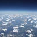
This is a page for my most challenging project...
I have implemented many serious projects until today... As a DIYer and Maker I love challenging tech projects... I have been thinkering on a HAB (High Altitude Balloon) project since many years but after seeing many on internet I had doubts on implementing one... Photography and especially astrophotography is my hobby... robotics and remote controlled devices are also my enthusiasm... I always wanted to take some photos of earth and high athmosphere but the job is tough... many people achieved HAB missions but had hard times leading to success... I have not seen a single successful HAB project on the first trial... the problem is I do not have a team of talented people helping me and neither I have resources for many trial and error attempts... But after all these years, now I have the time and courage for attempting a HAB mission... |
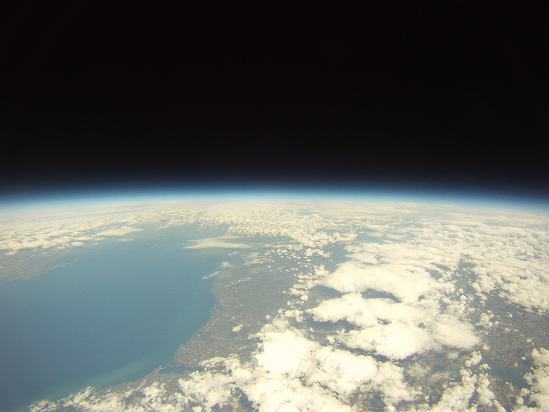
A HAB mission is taking a load to high altitudes by the help of a weather balloon which will burst at a specified high altitude in athmosphere, mainly around 20-30 kilometers high, and the load will fall back to earth... the "load" will be carrying some sophisticated electronics, cameras to take video and photos of earth... the electronics is mainly navigational, a GPS, microprocessor and tracking devices... the most challenging part of the mission is to get back the "load", i.e. the cameras and recorded images... mostly, the falling back to earth is unpredictable as of the location and the load can fall too far away from you ( may travel 100 km ) and you can lose all your equipment... |
|---|
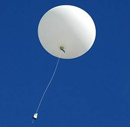
Most HAB missions which are done up till now is consisting of preparing some serious electronics and adding some cameras (mainly action cams) in a thick foam enclosure, which is mainly cubic and attaching a weather balloon (latex) filled partially with helium... the balloon size is determined by the weight of the load and amount of helium can be calculated with some formulas... you do not inflate the balloon fully because it will expand while ascending and will explode at the end at a desired altitude... A good weather balloon can rise up to 30 kms high before exploding... at that altitudes you cannot use GPS because it does not work over 18km high, you cannot use telemetry because long range rf tranceivers are too costly... I have seen some HAB missions carrying few thousand dollars worth of equipment... I do not have sponsors, nor I am that rich to risk that much costly equipment to lose... I have seen many unsuccessful HAB missions where the load has travelled much more distance than expected and could not be retrieved, some are retrieved after many days or months, some retrieved with too many damage... So my plan is a little bit different from standard HAB missions carried out up till now... The plan is to prepare a "load" which can actually come back to me... Mainly an aircraft with autopilot to soar back to my location after the balloon bursts and safely return home with images... Hopefully...
|
The job is challenging... the aircraft must be designed specially for the job... although I already have my own UAV, I cannot use such a plane simply hung under a balloon because of its shape... the plane which is lifted by the balloon will not be suitable while ascending and the wings will create problems... so I have to design a special purpose aircraft aerodynamically suitable for ascent, lifted vertically... also the autopilot uses GPS for navigation, which will not be usable until the returning aircraft reaches below 18 km... after the balloon bursts at 30km, the load will fall back to earth reaching high speeds which cannot be predicted beforehand... there are some online sources which can predict the trajectory of the mission according to given locations taking into account current weather and wind conditions, but those are all accurate at some percent, as far as I can see... and there are many issues I must take into account such as the distance travelled horizontally, mainly the power requirements of the returning aircraft... the batteries may not last long enough for the aircraft to reach home... anyway, I am hoping to build an UAV which will try to return, at least to some extent towards home... the tracking devices on the aircraft will help me retrieve the equipment safely while I am tracking it on the way...
|
|---|

Alternate Plans...
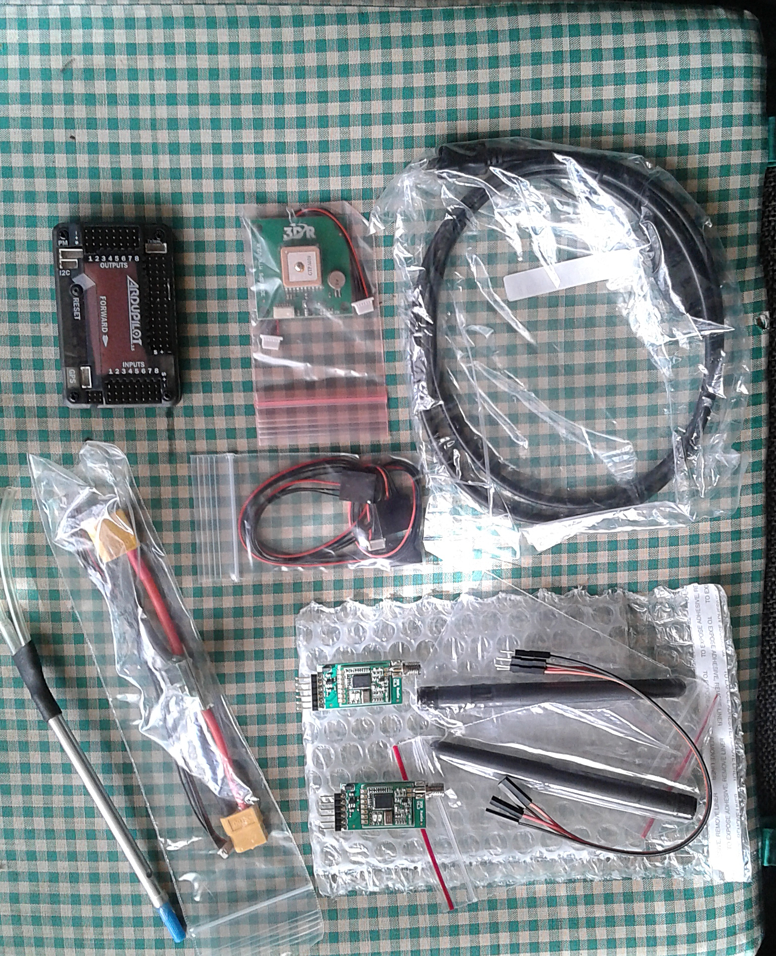
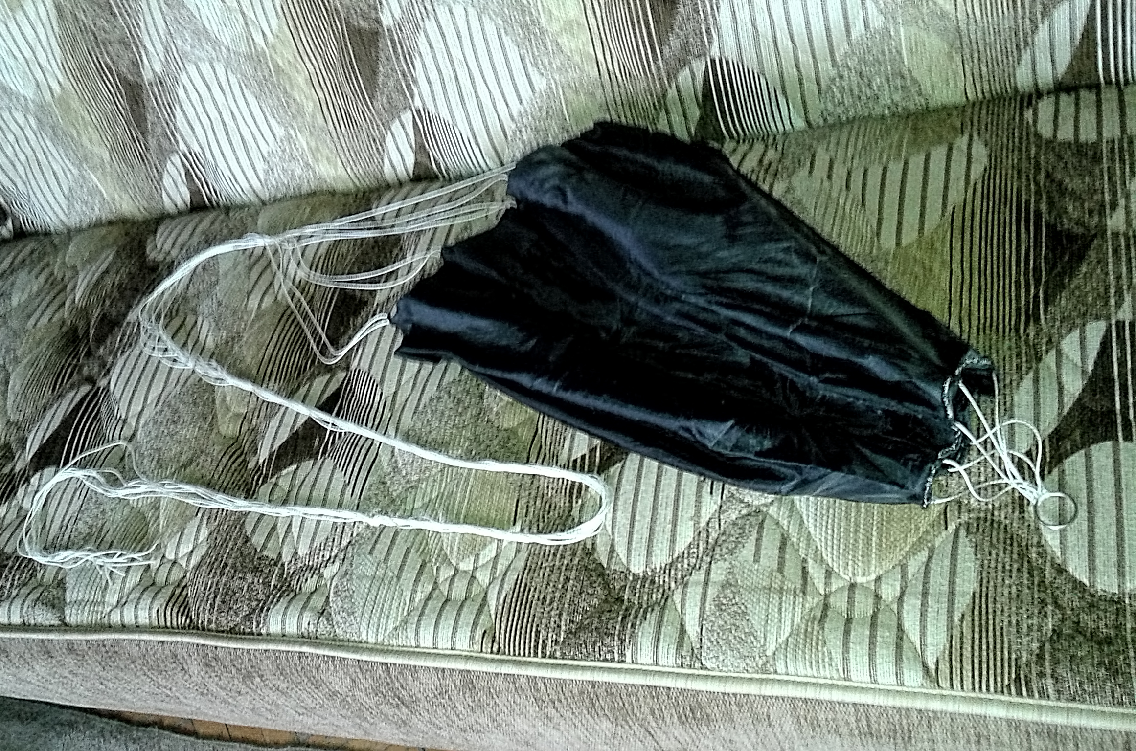
| There are some alternate plans in my head... plan A is to design an aircraft which has folding wings... the wings will be folded backwards while ascending and after the balloon bursts, some electronics will detect it and unfold the wings to stretched open position, enabling the aircraft in soaring position and activate Return to Home function ( Pigeon Function)... Plan B is to design an aircraft which has a more slim profile, small wings (perhaps a delta wing), compact enough to suit ascending... In both designs, there is the problem of freeing the aircraft from bursted balloon safely... the aircraft will be connected to the balloon with a wire from the nose and there is a problem to detach it completely... A release mechanism is needed... although the balloon will burst, there will be remaining material and some connection wires attached, which can cause tangling and trouble to the aircraft frame and propeller... | I am planning to use a full featured Ardupilot as autopilot, an action camera for image capture and an extra tracking device for emergency recovery purposes... A 5000 mah lipo battery will be enough to power the whole system, hopefully to finish the mission in few hours and return home... I will be tracking the trip on the ground on a laptop in a car... I will also have some temperature issues, falling down to -50 degrees celcius at that heights creating trouble for my electronics... I will overcome that by the help of some hand heating pads (chemical) which can be found on survival equipment stores... |
Some thinkering and design work on May 2016...
I did some thinkering on the project, especially on the design of the aircraft and realized that a folding wing design will be too complicated and adding extra weight and equipment such as strong servo for the unfolding mechanism... As an experienced DIYer I know that adding complex mechanisms to the system increases the risk of malfunction and things going wrong... So I almost decided to design a compact and rigid aircraft with a small wing profile... Some more research showed that such a successful aircraft design already exists... Burt Rutan's SpaceShipOne was launched for low orbit and successfully returned home winning the X-Prize in the past... I decided to design my aircraft on the basis of SS1, making some changes to suit my needs... I made the side winglets smaller and added a big rudder, also replaced the jet engine with a propeller...
|
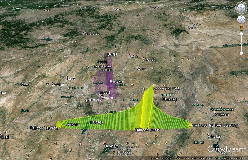
I also worked a little on mission trajectory prediction... There are many online sources on the internet for HAB mission planners, making good predictions according to weather conditions and showing the predicted trajectory on Google Maps... I made some simulations using different online prediction software on different times and successfully created mission trajectories... You can see on below image 2 trajectories on the same map and both shows few kilometer wide mission plans which is within reachable and trackable limits using a car... However I have seen many HAB projects on the web showing 100km wide missions and many unsuccessful ones with lost equipment... So I must not rely on these online HAB Mission Predictors on the web... They can give you a rough estimate before you launch... I have to design a fool proof system...
|

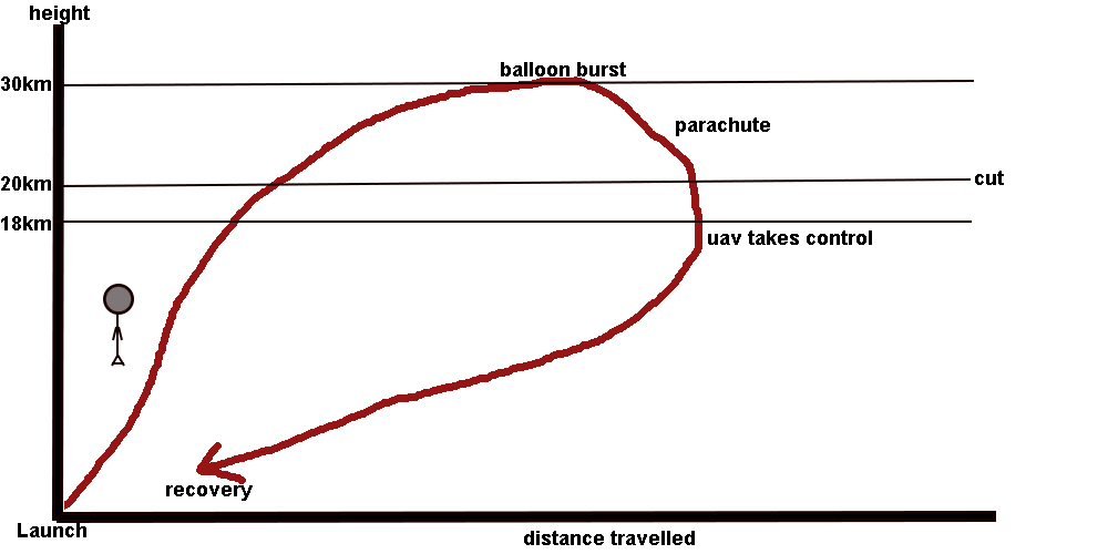
The global plan looks ok... Launch the shuttle tied under a latex weather balloon. Wait until it bursts at around 30km above earth. Parachute deploys and free fall. Main navigation MCU monitors height. Parachute wire is cut at 20 km. Autopilot is engaged at 18 km and UAV gains control of flight to return home. Autopilot brings the shuttle close to me until we meet (hopefully). I gain control of the shuttle by disengaging the autopilot and safely land it...
|
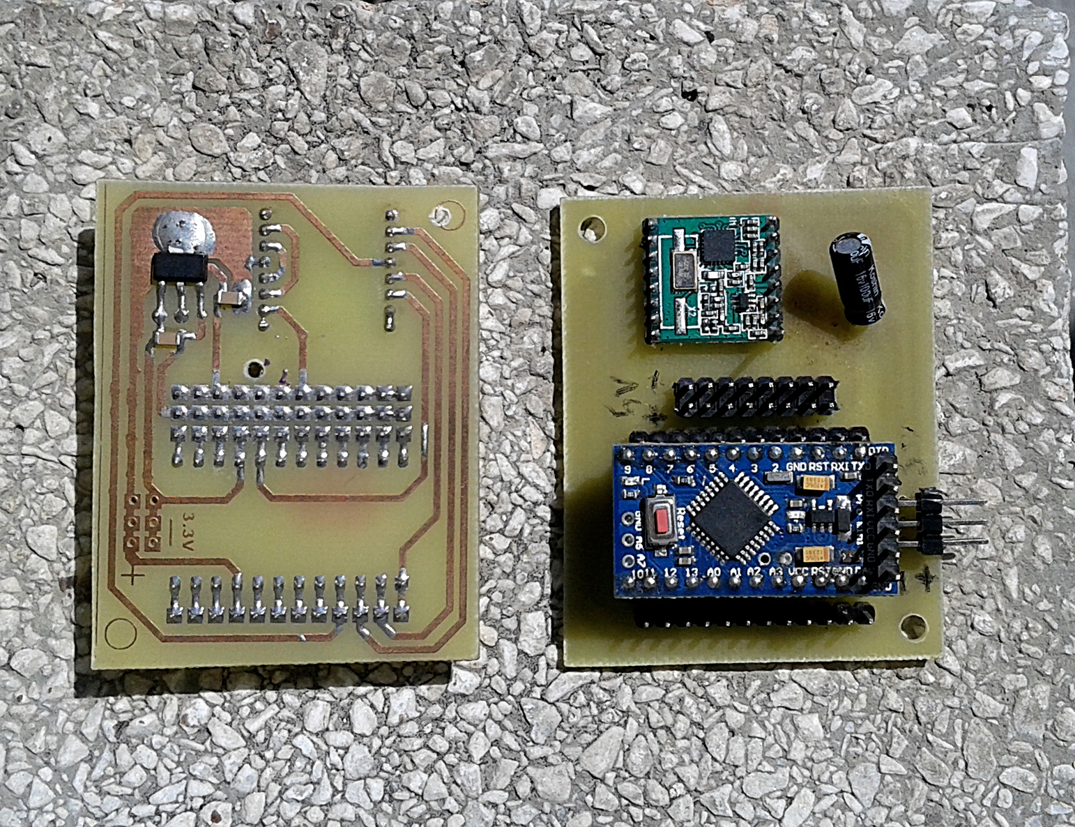
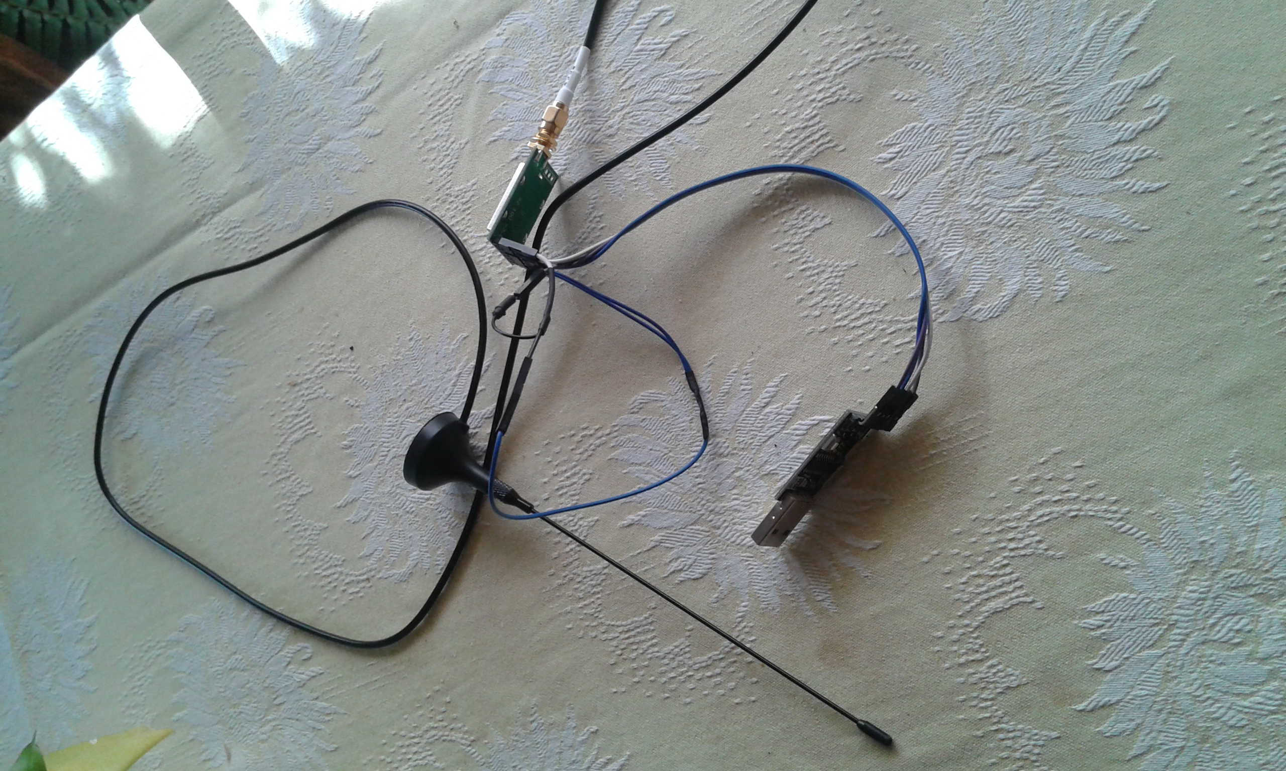
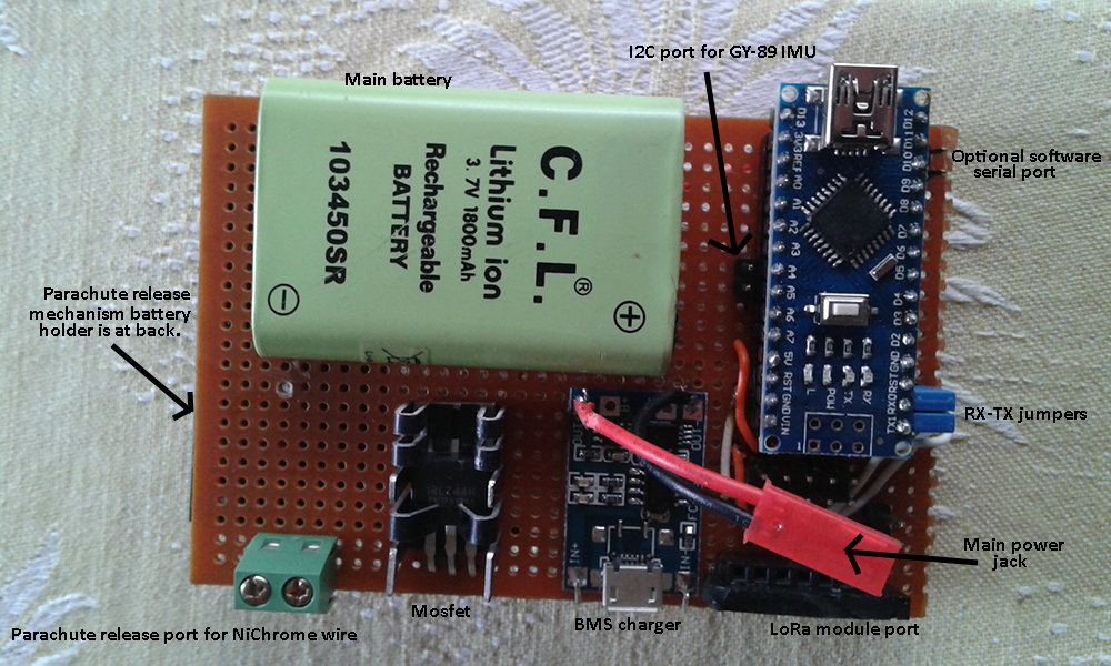
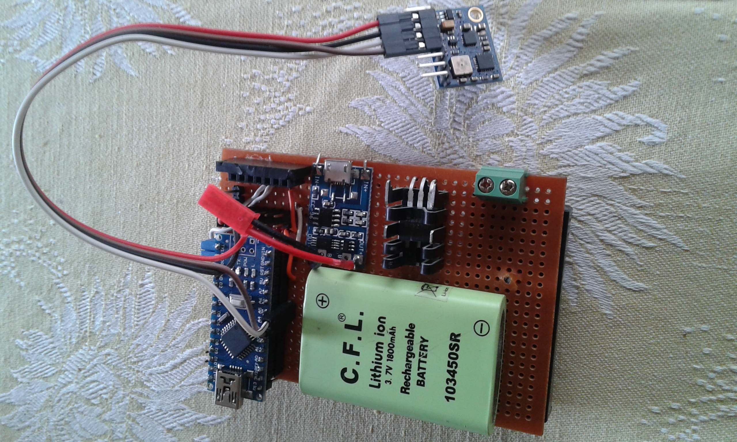
Here we have some of my equipment ready... The homemade parachute, the Ardupilot set and the wire cut mechanism and electronics. Ardupilot set has its own telemetry system (3DR Radio set) but it is useless weight on the shuttle because of its short range. So I decided to use LoRa modules which I have already at hand. Main flight computer will be these small modules implemented with tiny Arduino Pro Minis and HopeRF RFM96W lora modules. The main flight control computer will have its own 10 DOF IMU for navigation... It will control the flight phases, cut the wire and engage autopilot when time comes...
|
Update on February 2017:
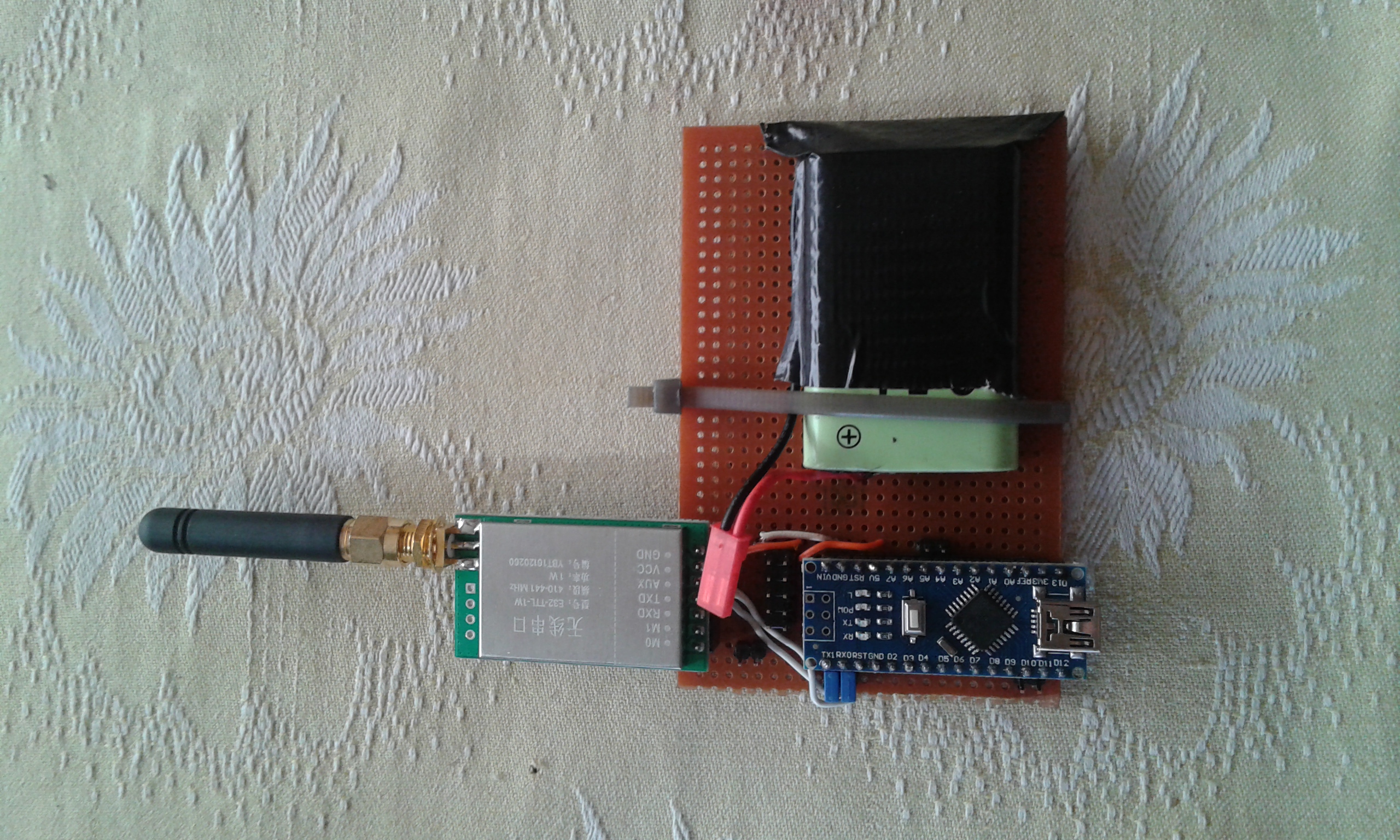
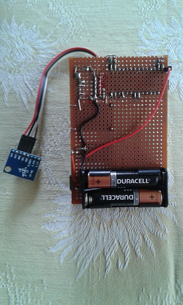
The tests of my LoRa modules were not promising. I spent too much time on getting these modules work properly. The problems were mostly about the SPI software library and range. Then I found some new LoRa modules based on SX1278 chip and UART interface (easier to write software), moreover these modules are said to have a longer range. My new LoRa modules arrived from China and I prepared a new set of transceiver sensor nodes with them. These uart modules manufactured by E-Byte come with different power options from 100mw to 1W (20dbm vs 30dbm) and I prepared a transmitter using 1000mw and receiver 100mw. The sender module will be on the aircraft and will be more powerful. Receiver sensitivty of the modules are the same so I made my receiver unit with 100mw module. I made a simple range test with my modules, placing my transmitter unit on my terrace powered up with a 1800mah li-on battery, taking my receiver unit with my laptop and went to the other side of the city, a far away hill with a citadel on top. On top of the castle there was a high wall with a cafe and I was excited to wait my laptop to power up. Plugged in my receiver unit and run my serial terminal program, upon choosing the com port I was so happy to see the telemetry data flowing on the monitor. The test was successful, I was surprised to see that telemetry data was incoming without any delay from a distance of 5km. I did not make any modifications in the setup and default setting with 9600 baud data transfer with 2400 baud air data rate was working flawlessly. No delays, no errors. I am sure that decreasing the baud rate and increasing the delays can result in much much more range. When I arrived back home after 3 hours, the transmitter module was still working.
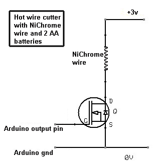
Then I completed the main flight computer board adding the parachute release mechanism and the BMS charger module. As you can see from the above circuit, the parachute release mechanism is complete and tested. I used a IRLZ44N logic mosfet to trigger and cut the nylon rope by the help of 5cm NiChrome wire. 2 AAA Duracell batteries are enough to cut the rope in less than 10 seconds. A mosfet instead of a relay is used because this way less components are used in the circuit. Tested... I also added a BMS module to safely charge and discharge the LiOn battery. I am happy about the result...
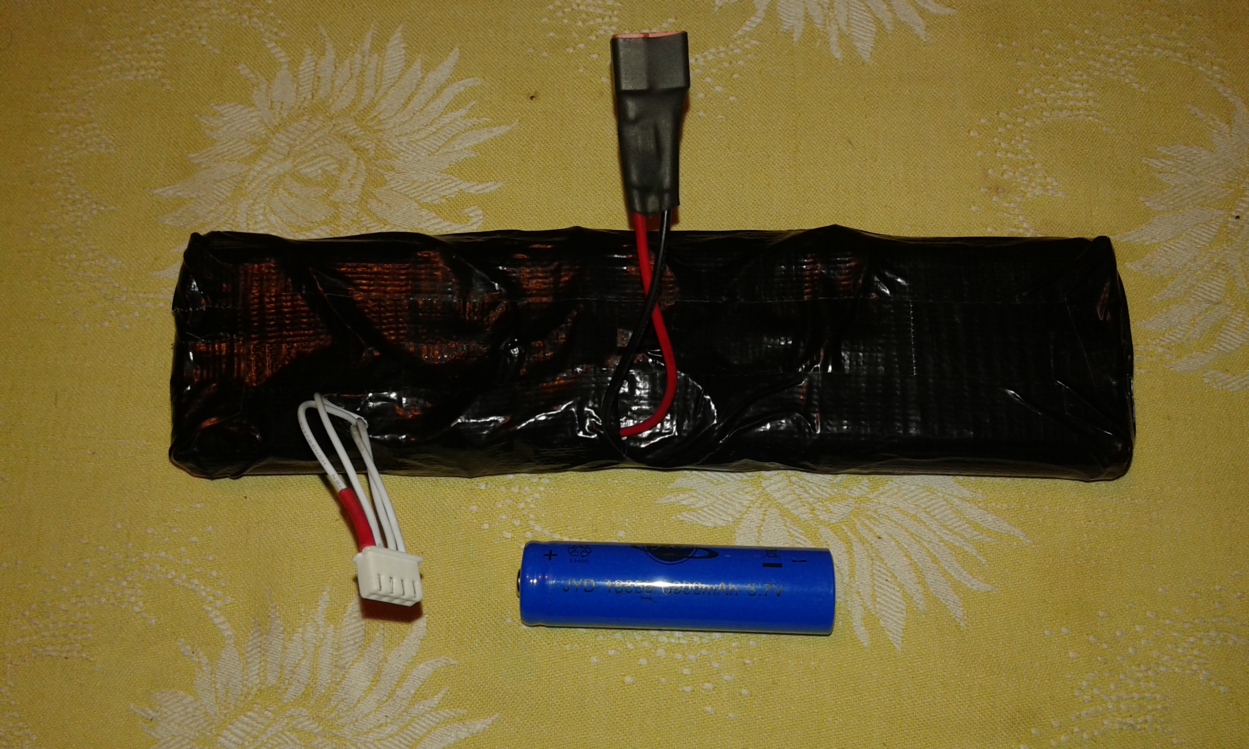
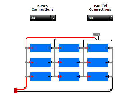
After thinkering on the main power supply for the UAV, I also decided to use a pack of 18650 LiOn cells on the system instead of LiPoly packs. At first I planned to use a 5000mah 3s LiPo pack which I already have at hand. However these LiPo packs are too heavy and dangerous to use. Some research on internet made me think over new 18650 LiOn cells which are widely used together to make light and powerful packs. These cells are mostly used with a BMS board which protects the cells and manage charge and discharge during usage. However if you have a good balance charger these cells can be packed together just like LiPos and can be used with a balance lead and power lead. I made my power pack using 9 cells in a 3s 3p setup. Due to my budget restrictions I ordered 9 Chinese make cells and they arrived with 6800mah stickers on them. I surely know that this is not true and these cells can be around 2650mah each. I made my DIY battery pack and prepared a custom horizontal setup for ease of placement inside the UAV. Now I have a 7500-8000mah 3s power pack weighing only 400 grams...
Some brainstorming on the UAV fuselage, May 2017... I realized that I have to make a lot of test flights and that means a lot of landings as well. The landings will be on body and the propeller will get broken everytime. So I started to think that I have to re-design the fuselage and have the motor on top, like a pod. However I still have to consider a slim body design and the best answer is a ducted fan on top. This will allow me to design a flat bottom body for easy landing. Something else I realized that my UAV will be towed up connected to a rope and parachute, there will be forces on the fuselage when released from the balloon and also later, the parachute. This means I need a rigid connection and hold all around the body of the aircraft. The single point rope connection on the nose must be rigid enough to distribute the forces evenly on the body. A simple brainstorming ended up in a cylinder frame with added small delta wings. With the thruster and all control surfaces on top, the most plausable design looks like a space shuttle. The main body will enclose all electronics and have an aerodynamic design, connected rigidly to a rope at front nose. This made me think of a PET bottle which has wings at both sides and a ducted fan thruster on top. So that I can make a single rigid rope connection at nose which will carry the whole weight of all electronics inside a confined body. Now I have to accomplish such a new design for my UAV fuselage...
 |
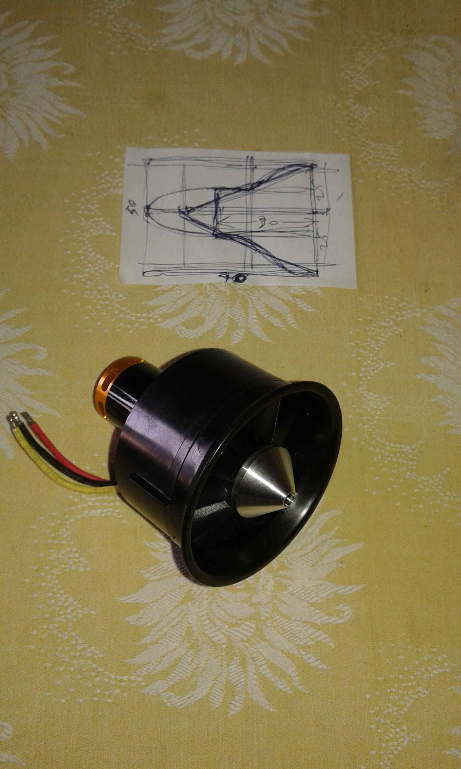
Update on June 2017: Well... The design of the fuselage continues and I realized that it should be more compact, less moving parts and durable for rough landings ( I have to make many tests and it will make many rough landings on body). So I thought that the propeller at the back will be destroyed in every landing. It also has possibility of tangling to parachute ropes or towing rope. The best solution is a ducted fan jet motor on top of the body. This will help me to design a clean bottom design with a nice landing surface. After trying many motors and fans, I found this beast for my project. This is a 12 blade EDF unit equipped with a QF2822L 4300KVA motor which can create 1600gm thrust with a 3S Lipo battery whis is well suited for my design. I will now go for a more X-Plane type of fuselage design, sleek and EDF thrust unit on top. There are many high speed model fun jet designs I can get inspired. A space shuttle type design will also be feasible. I will now work on the new fuselage design and make a lot of tests. The design must be easily implemented, easy to manouver and be controlled with my Ardupilot... |
 |
|---|