 RepStrap 3D Printer Page
 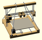 RepStrap 3D Printer Page
Always wanted to own a 3d printer... But as a maker and DIYer I wanted to build one myself. So I plunged into the world of 3d printing without hesitation. As a newbie to the technology, I made a comprehensive research on the web and assured myself about the feasibility of building a 3d printer. First I had to decide about the type of machine I will construct. Many people on the web built their own printers and I read about their experiences. Prusa appeared to be the most common design. Developed by Josef Prusa, this design proved to be the most versatile one. The plans and necessary materials were scattered all over the web but the trusted info was on the RepRap.org site, which is the current home of reprap... The name reprap is created from the idea of "self replicating manufacturing machine", in other words, a machine that can replicate itself. The reprap community makes their own printers, share their experience and help others to build their machines. This is also an ever growing community. So I had to take part in it...
Urging with the desire to own a 3d printer I began sourcing the necessarry parts through the web to build my printer. First I decided on the electronics, selecting Ramps 1.4 controller just because of the fact that it is Arduino based. I am too familiar with arduino microcontrollers with my robotics background. I collected the necessary electronics mainly from Chinese suppliers due to budgetary concerns. Next comes the hardware part of the project which is rather standard among the reprap community. At that point my DIYer dna popped out and I realized that this is not the usual approach that I should follow. I am a DIYer and a Maker and I felt an irresistable urge to complete my build as one...
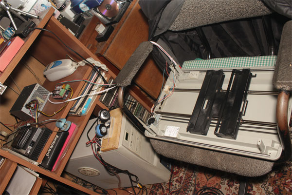
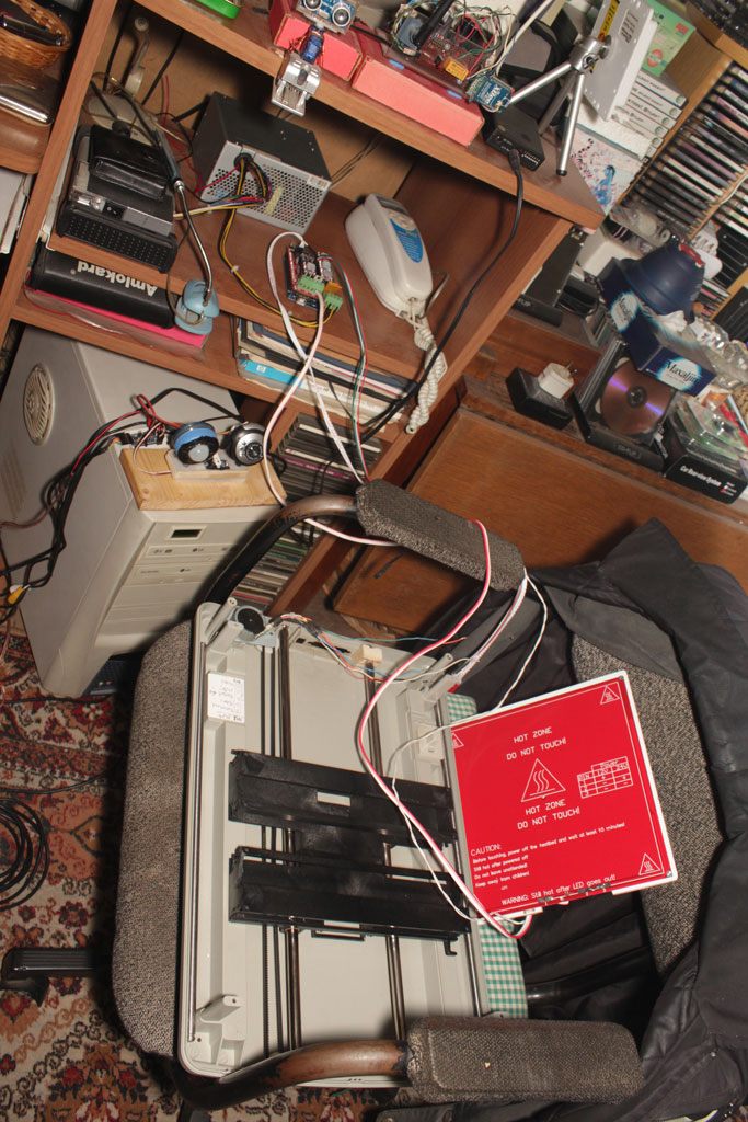
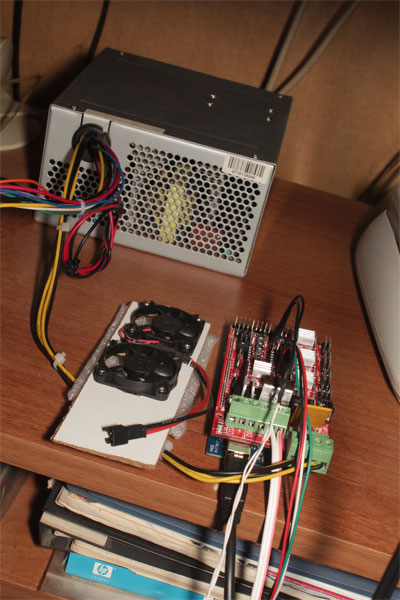
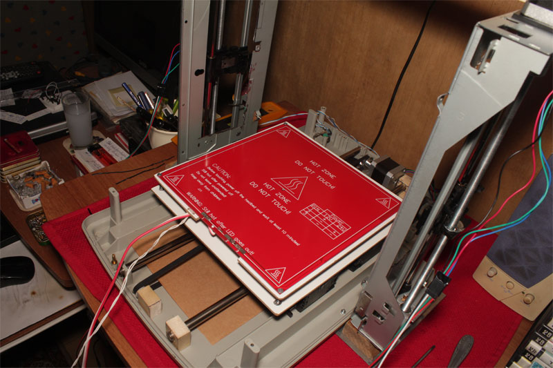
So I started to make my own plan. After few days of tinkering I remembered that I had one flatbed scanner and an inkjet printer scrap lying around which I kept for a cartesian project like this. They had the necessary axes, rods, belts and motors ready to scavenge. Disassembly and inspection showed that the idea is feasible. However it did not take long to realize that the motors of the scrap is far from capability as of torque and some rods and belts were missing. So I returned to web sourcing. Luckily I found similar items in second hand stores on the web at scrap value, this reminded me of the saying "someone's trash is other man's treasure". Now having 2 sets of flatbed scanners and 2 sets of similar inkjet printers I have all the axes hardware but more scrap at home... As an experienced DIYer and Maker it didnot take me long to complete all the electronics and some base of the printer. Built and tested Y-bed and Z axes. Just a little note: 3D printer utilizes a heated bed, 4 nema17 stepper motors for the axes and an amps hungry extruder which also has a heater and stepper motor on it. This means that you will need a power source which can supply many amps of voltage. The simple solution is an ATX PSU which is an amazing device for us DIYers. A 400W ATX PSU can easily deliver more than 20amps and it has many different voltages on it. It can supply +12v, +5v, +3,3v and -12v, -5v which makes it a very versatile lab power supply. There are many instructables on the web describing how to convert and use it...
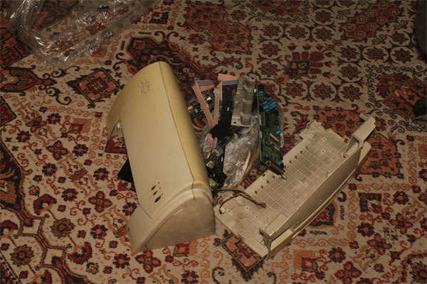 |
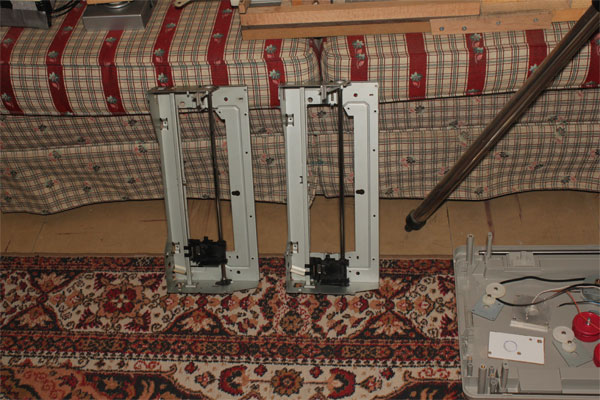
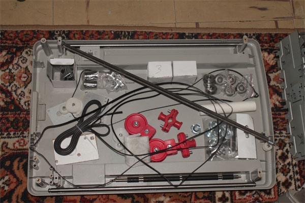
Left is my scrap Apollo inkjet printer and right is my Compeye Simplex flatbed scanner lying around... With the help of second set of scraps, I managed to build a y-bed with 2 guiding rods and 2 similar x-axes ink carriages of twin inkjet printers proved out to be rigid verticals for the z-axes... | 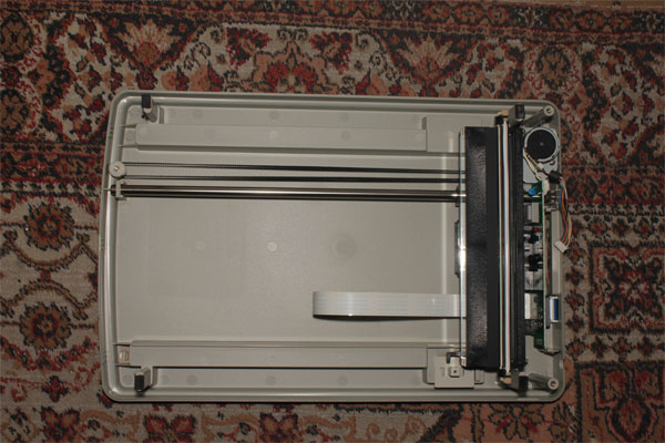 |
 |
 |
 |
 |
 |
 |
As of Feb 2014 I am now waiting for my stepper motors to arrive for further axis construction... In the meantime I am planning the X axis and extruder connections...
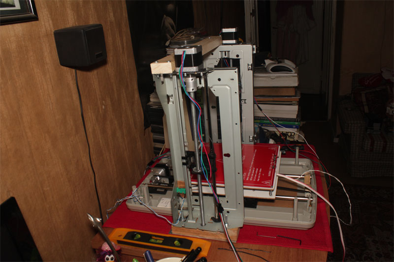
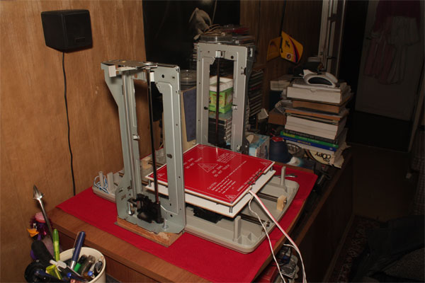
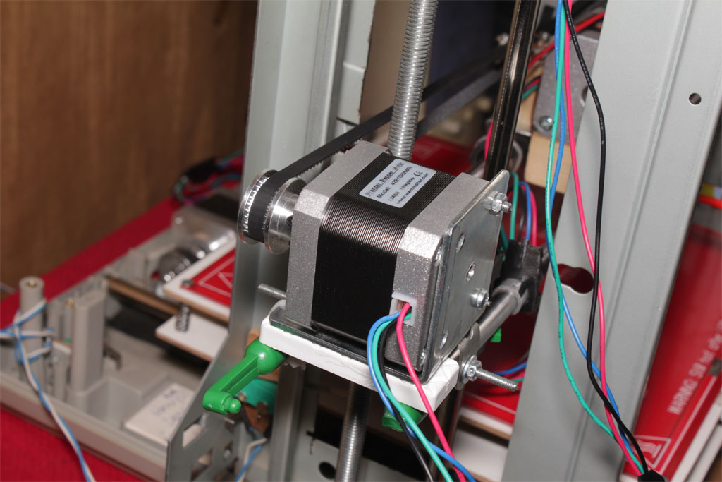
On 19th Feb my motors arrived and it took me just one day to mount them on both Z and Y axes. Calibration and alignment was the hardest part. If you are building something custom, the problem is you have to fight for every single detail. I used 28tooth pulleys and T2 belt for the Y axis and a little math was needed to calculate steps/mm [steps/mm = (motor_steps/rev * driver microstep) / (belt_pitch * pulley_no_of_teeth)] which is critical. Your axes must travel exactly 10mm when they are instructed to move 10mm... Now I have perfectly working Y and Z axes... Buildup continues...
 |
|
 |
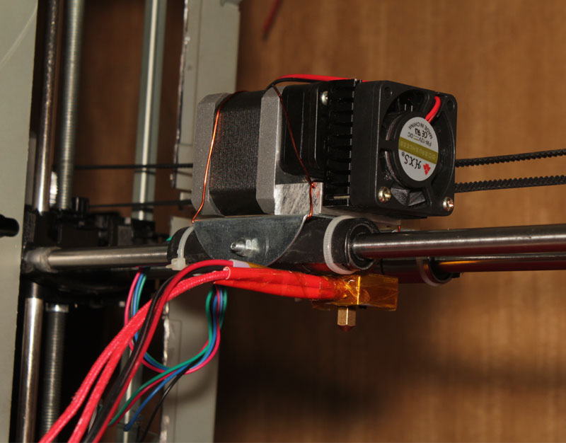
Update on April 2014: At last all my parts arrived and I had the opportunity to design the x carriage... I built a temporary X carriage for the extruder assembly... In the end this is a RepRap and I will use the 3D printer
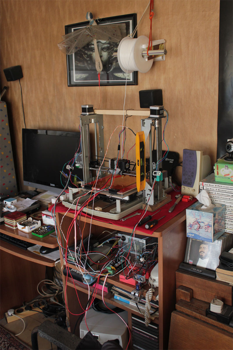
to build some of its parts itself. Once it gets printing, the first part will be the extruder carriage... Because its the most complicated part... Now it is a mess of cables and ready for test prints...
 |
|
 |
 |
Managed to make some test prints... Still tweaking with settings... Prints are getting better... These prints may be looking silly but I am proud of them after all the effort I made building this 3d printer from scratch... | 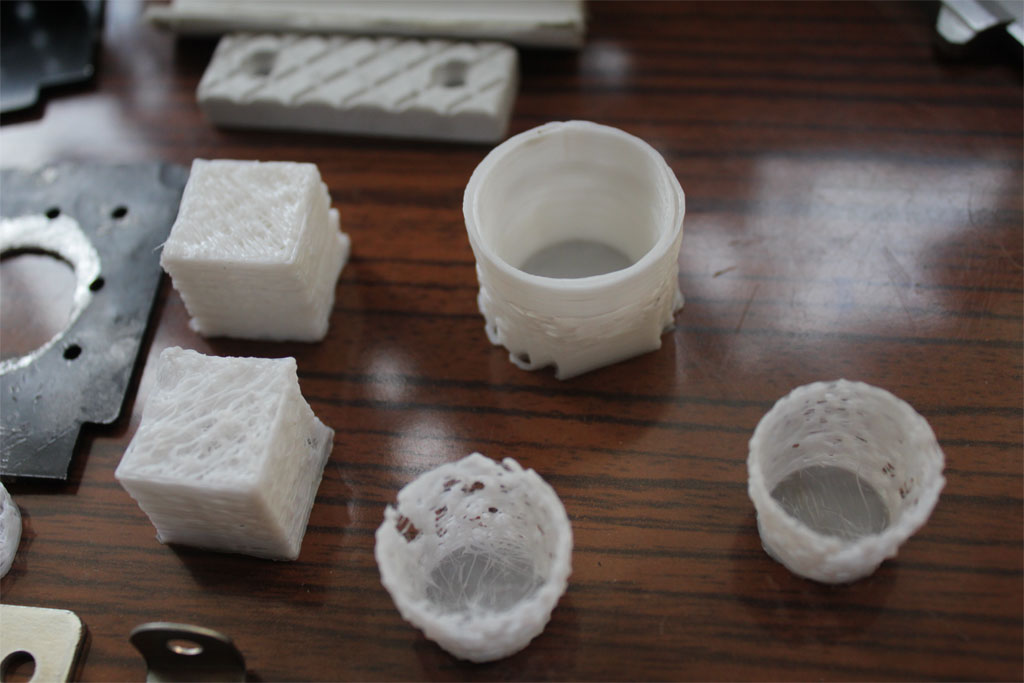 |
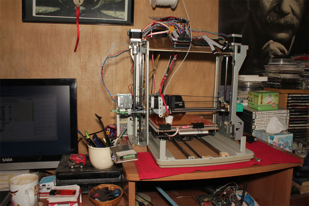
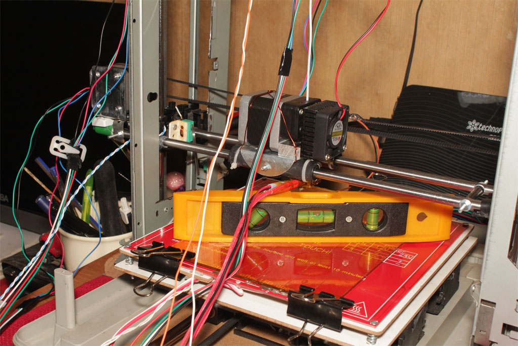
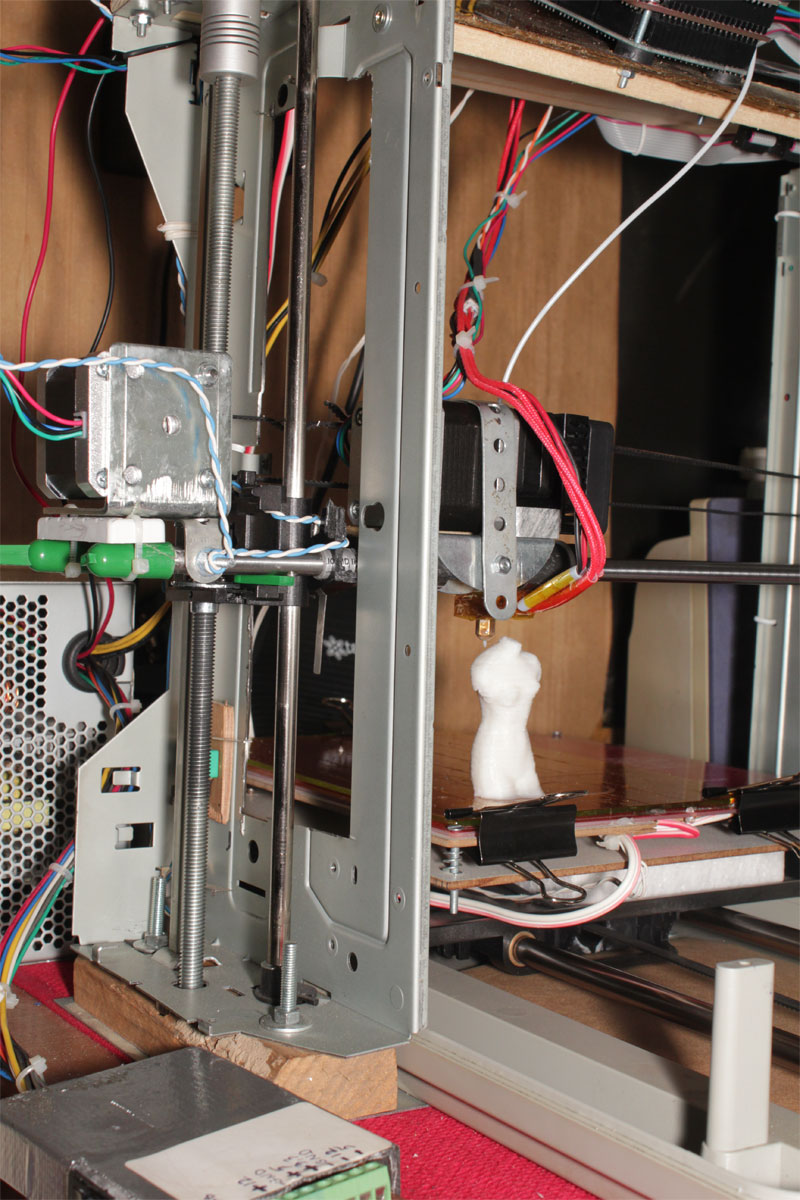
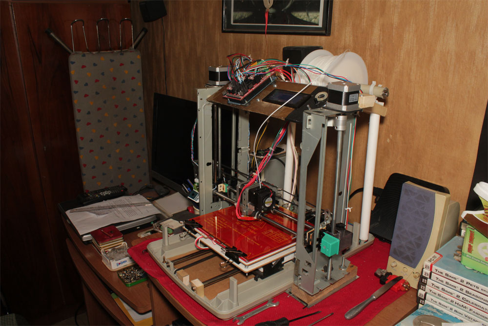
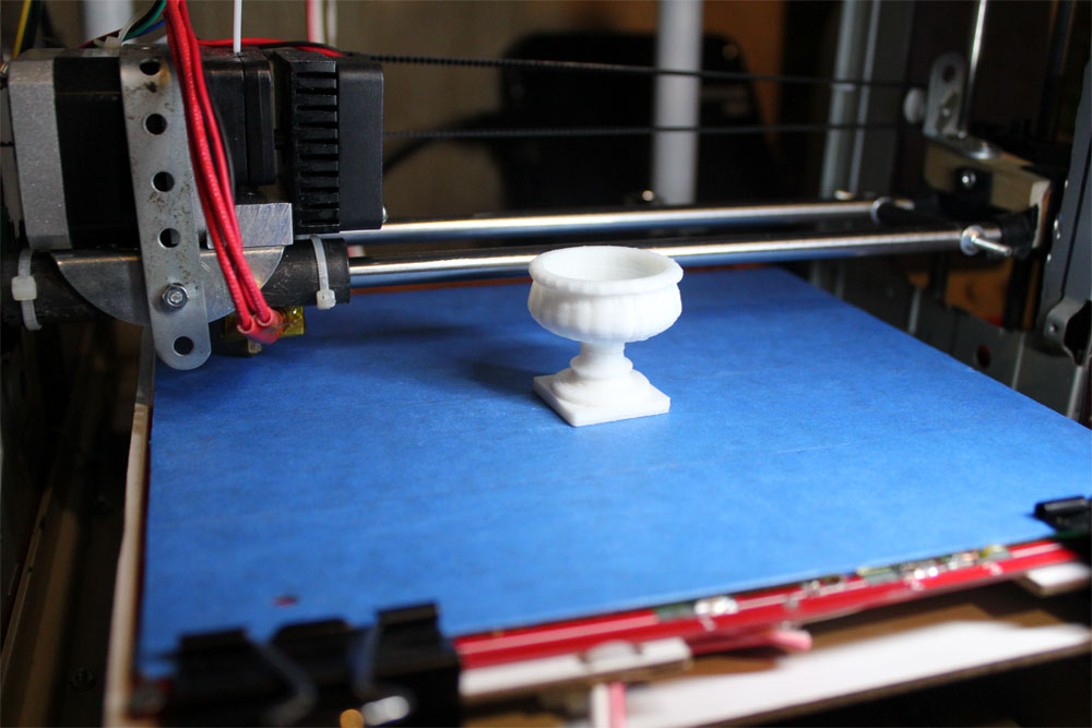
After tweaking a lot with settings, I started to make decent prints now... Time for tidying up the cableware... As you can see I added a stand at the top of the printer and moved all electronics to this plate... Wires are cut short and cablezipped... Now my printer started to look like a real one... I also strengthened the extruder carriage assembly by tightening the head with metal rails... This contributed a lot to the quality of prints... Top pic shows the latest appearance of the machine with a tiny bonsai pot printed for my miniature garden... Right you can see my last print, a Milo Venus sculpture freshly printed... |
 |
 |
 |
Nowadays I perfected the printer settings and upgraded to latest Marlin firmware. I also began to use blue painter's tape which helps in sticking of the first layer better. I added a USB led light for night printing. While test printing I happened to own many miniature garden ornaments. Applications on my garden pages... | 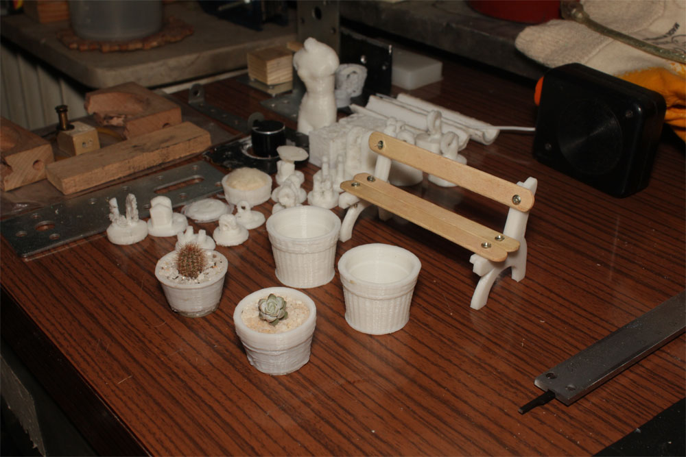 |
 |
Printing of tiny objects continues... In order to test resolution, I keep on printing small and detailed objects. These two 3DMax meshes resulted satisfactory... Both objects are very detailed and 2-3cm wide, layer height 0.2mm... | 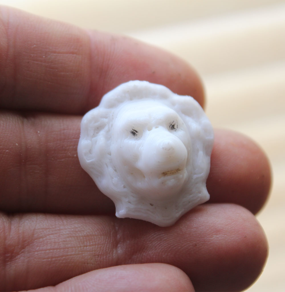 |
 |
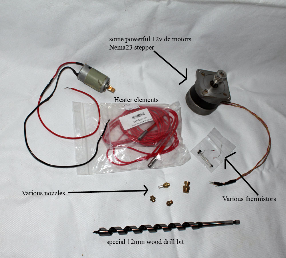 |
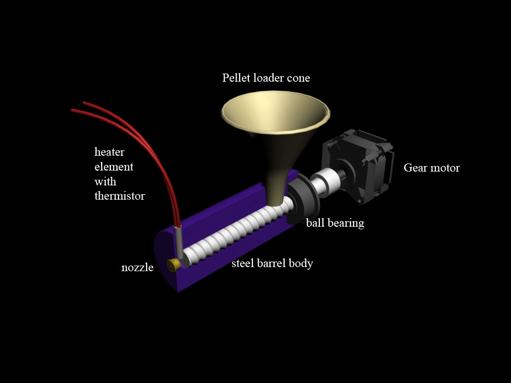
- We all know that filament is the most important part of 3d printing... And we also know that these are neither cheap nor easily accessible... So I decided to make my own homemade filament extruder. After some research on internet, I decided to use this simple design which is the core of many commercial filastruders. I prepared a simple CAD model for you to conceptualize the design easily. All these parts are easily found at every DIYer's parts bin. Only serious design I made is the steel barrel body which is now being made by one of my friends who has a lathe. As can be understood, plastic pellets (or small cut plastic) is loaded from the upper cone and the screw carries them to the front where they are being melt and forced out of a brass nozzle (a natural gas or propane nozzle mainly) to form a filament. According to my calculations system can be driven with a powerful dc gearmotor or a big stepper like the one in the pic (nema23). Even a household drill can drive the system for few hrs... I designed the system to make 1.75mm filament and found nozzles that can do the job. the radius of output filament can be monitored by a sensor for accuracy but I do not think I will need that as long as the shaft is driven at constant speed... As for the heating control, I decided to use the same ceramic 12v heaters and 100k thermistors used in reprap printer extruders (actually there will be more than one on the front end around nozzle). There are simpler and cheaper solutions for heat control, such as constant temp PTC thermostats but as the name implies these are made to keep the heating at a predefined constant temp. Actually I want to make tests for different types of plastics ( including waste plastics such as PE bottles) that is why I decided to have Arduino controlled heater&thermistor combination under PID control because various plastics will need different melting temps...
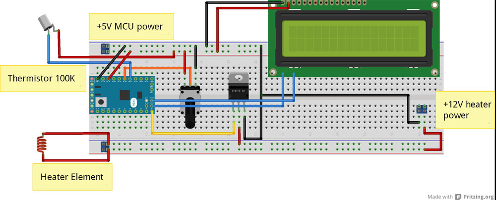 |
Finished making the heater controller... Left is the Fritzing image of the circuit and right is the actual implementation of the controller while testing... It works like a charm... Here I share the Arduino script which I wrote for the purpose... Anyone interested can download the script... It is open source, but please give proper credit and link if you use or share... | 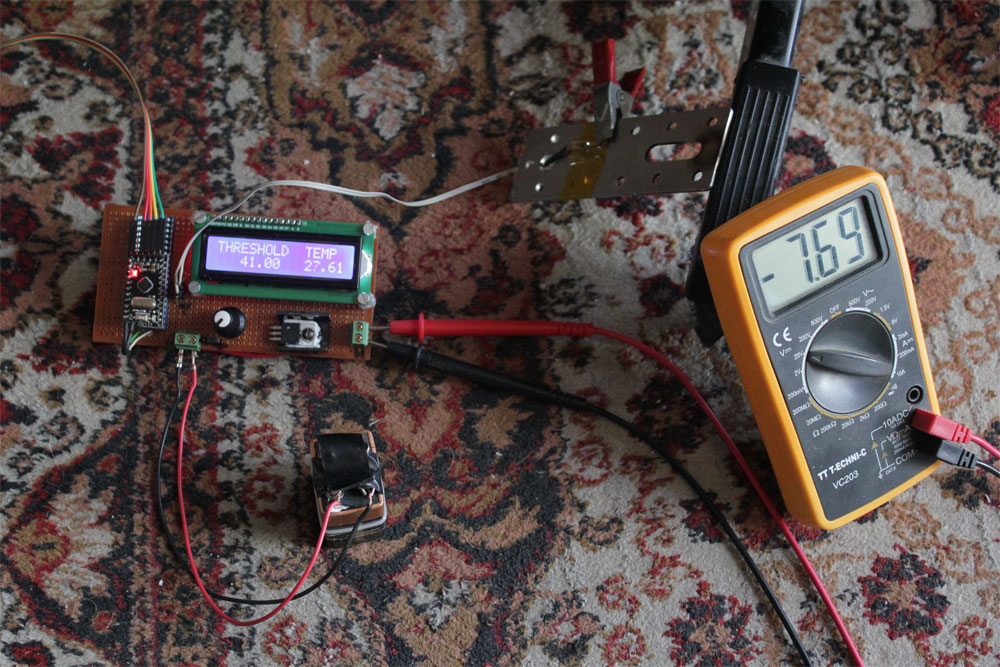 |
 |
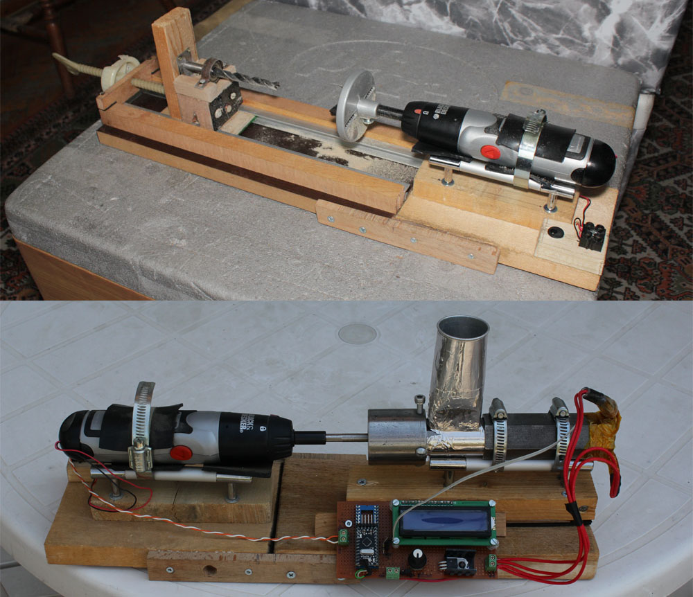 |
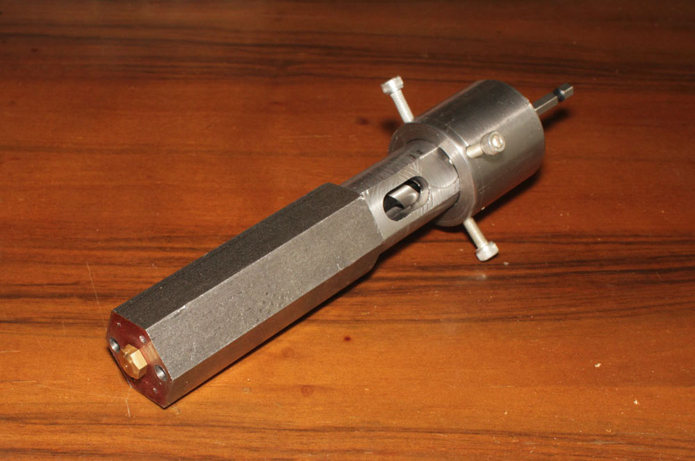
- My metal body assembly came from milling... Seems that my friend did a good job on this part, with adjustable back cover holding 2 roller bearings and replaceable driver screw. 2 different screw bits with 2 sizes, mounting holes in front for the heater elements and replaceable front end. I am planning to mount this unit to my wood lathe which I made some time ago. I will replace the idler part of the lathe to drive the filastruder. The batteries of this low rpm screwdriver was dead long ago and I recycled it as a high torque wood lathe driver working with a 6v 2amp power source... So my good old wood lathe will be a multi-functional tool from now on...
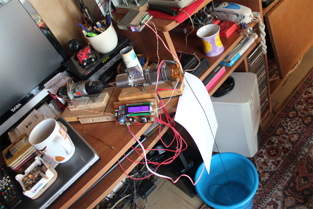 |
At last I found some time to test my new filastruder... PID values are 200 degrees at +-5 degrees for the recycled plastic... 1mm nozzle created a usable 1,70mm filament... The old screwdriver did a good job too... I placed a bucket full of water for cooling but it was not essential... The filament cooled well after leaving the nozzle around 30cm... | 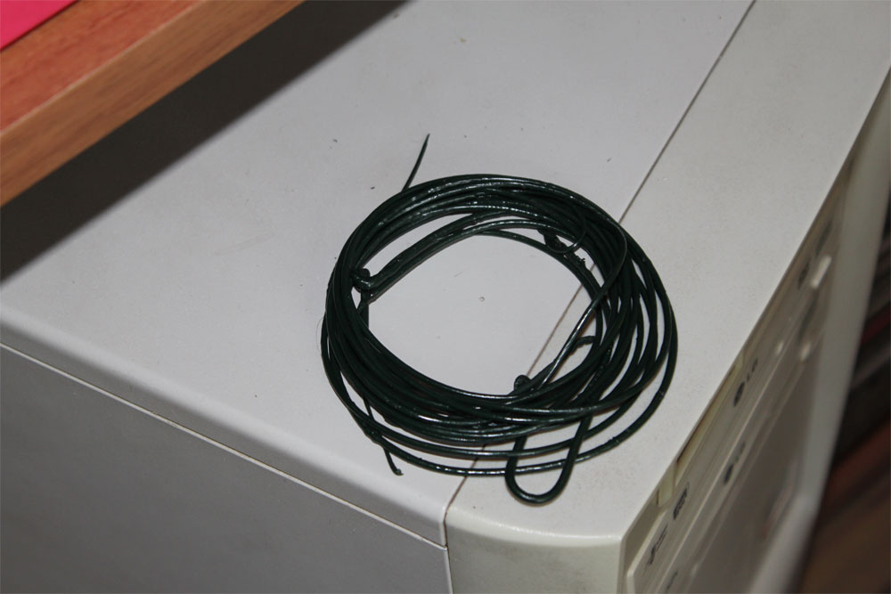 |
Video of my filastruder in action... First test run with recycled plastic pellets... YouTube link: HERE...
please e-mail to me at dhepguler@hotmail.com

 RepRap.org... Home of reprap...